This is just a temporary page to host some of the discussion points that have come from a post on the cyclinguk.org forum. It was suggested in a thread that it would be pretty simple, or straightforward to convert a non-disk Rohloff hub to a disk compatible hub. I said that this was a dumb idea and potentially dangerous to be suggesting that it could be attempted by someone without a decent amount of experience. Messing with bicycle brake components is obviously something we should be careful of. The thread became quite messy and combative. To try and further explain why I thought it was a dumb idea, I decided to actually put some time into modelling a potential solution. The idea was to try and illustrate what a complicated process it could be. Bear in mind that Rohloff (or a service centre) will do this conversion for you by replacing the hub end cap (and converting to external gear mech if needed) and your warranty will be maintained. That’s a big part of why I think attempting a DIY verions of this is a dumb idea.
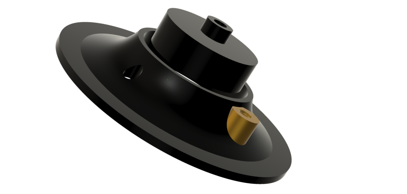
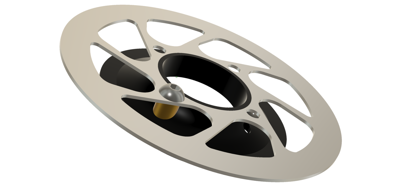
This is the crux of the initial design suggestion. The idea is to mount 4 ‘pedestals’ to the hub end cap. This end cap is removable from the hub so the internal area is available to us. The use of 4 pedestals was so we could use the Rohloff spec rotor which has 4 bolts with a BCD of 65mm and an internal bore of 52mm (which will later make things tricky). At this stage, we don’t know how the pedestals are going to be fixed to the hub.
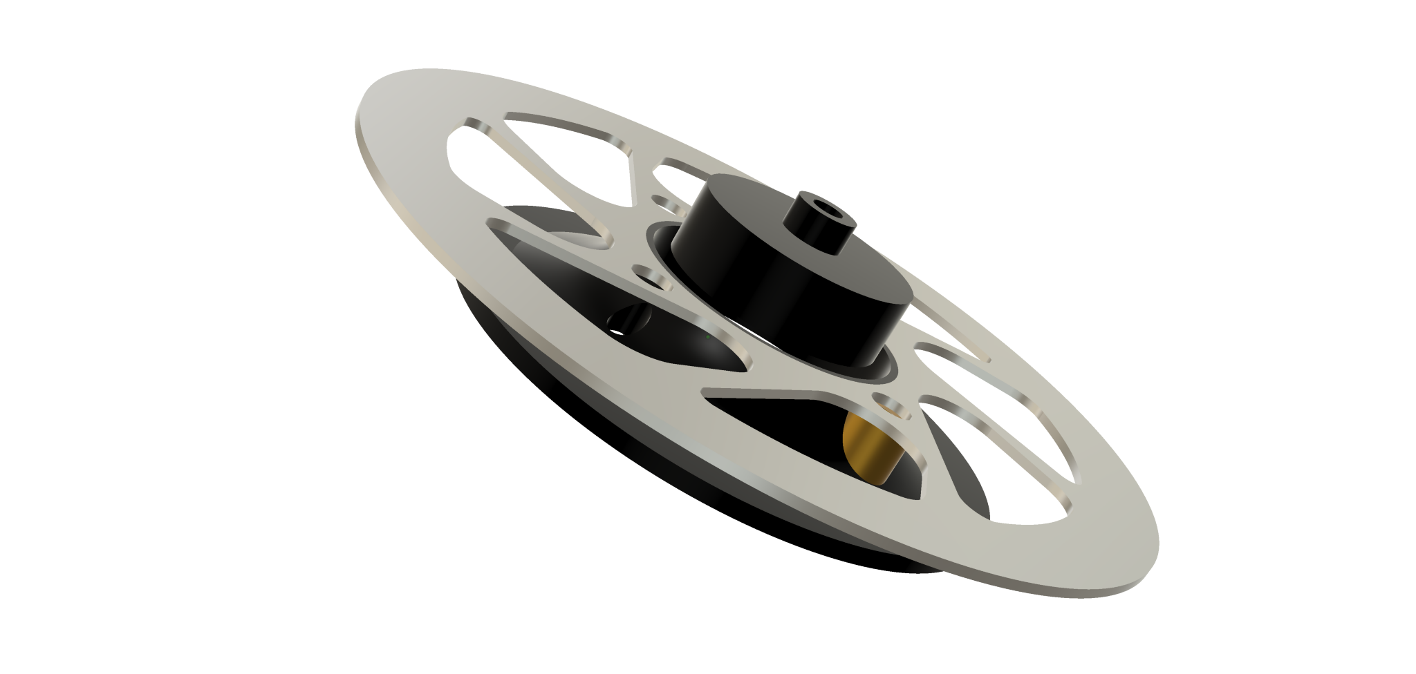
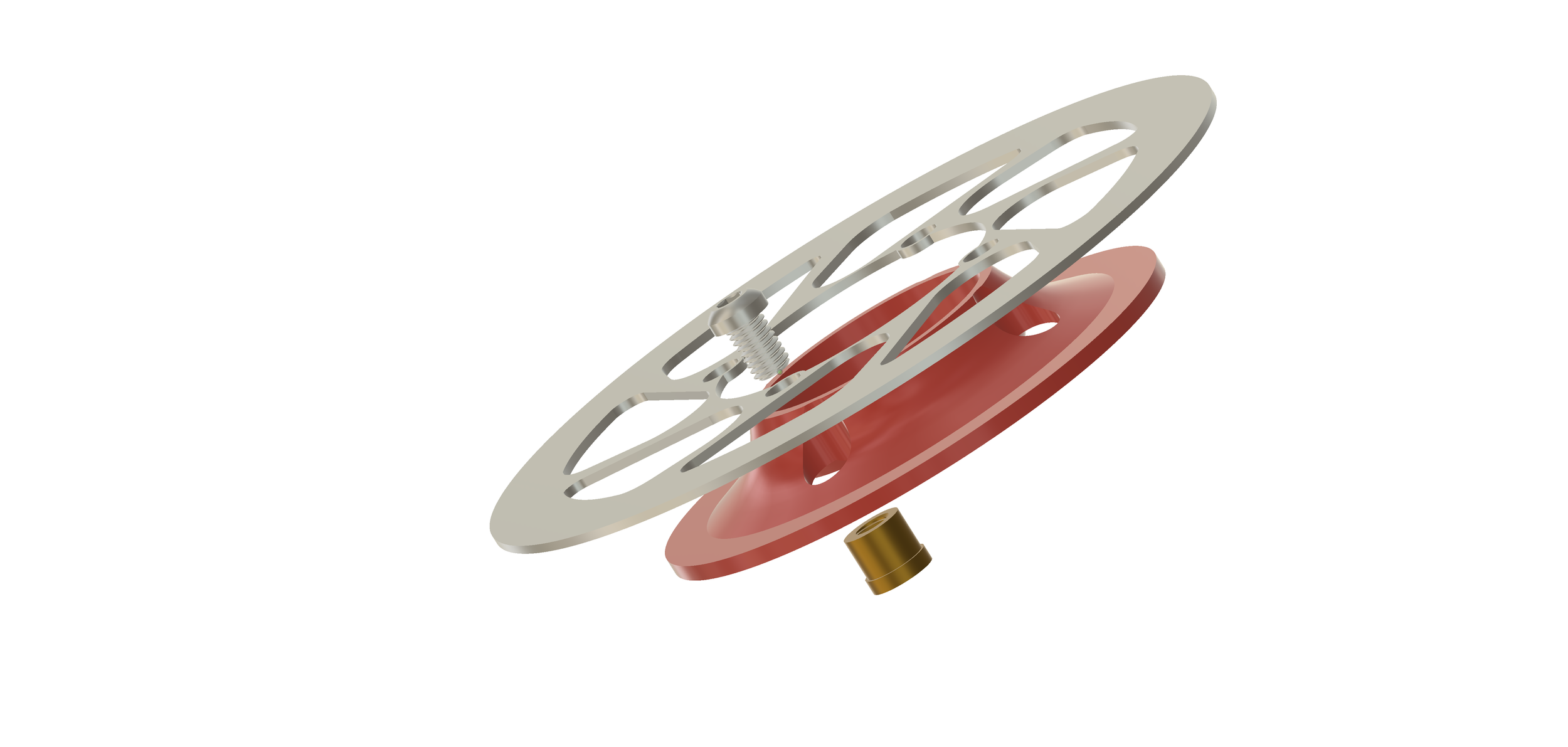
This is a view of the whole assembly; rotor, pedestal and hub end cap.
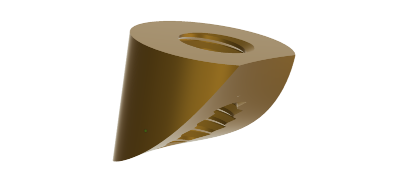
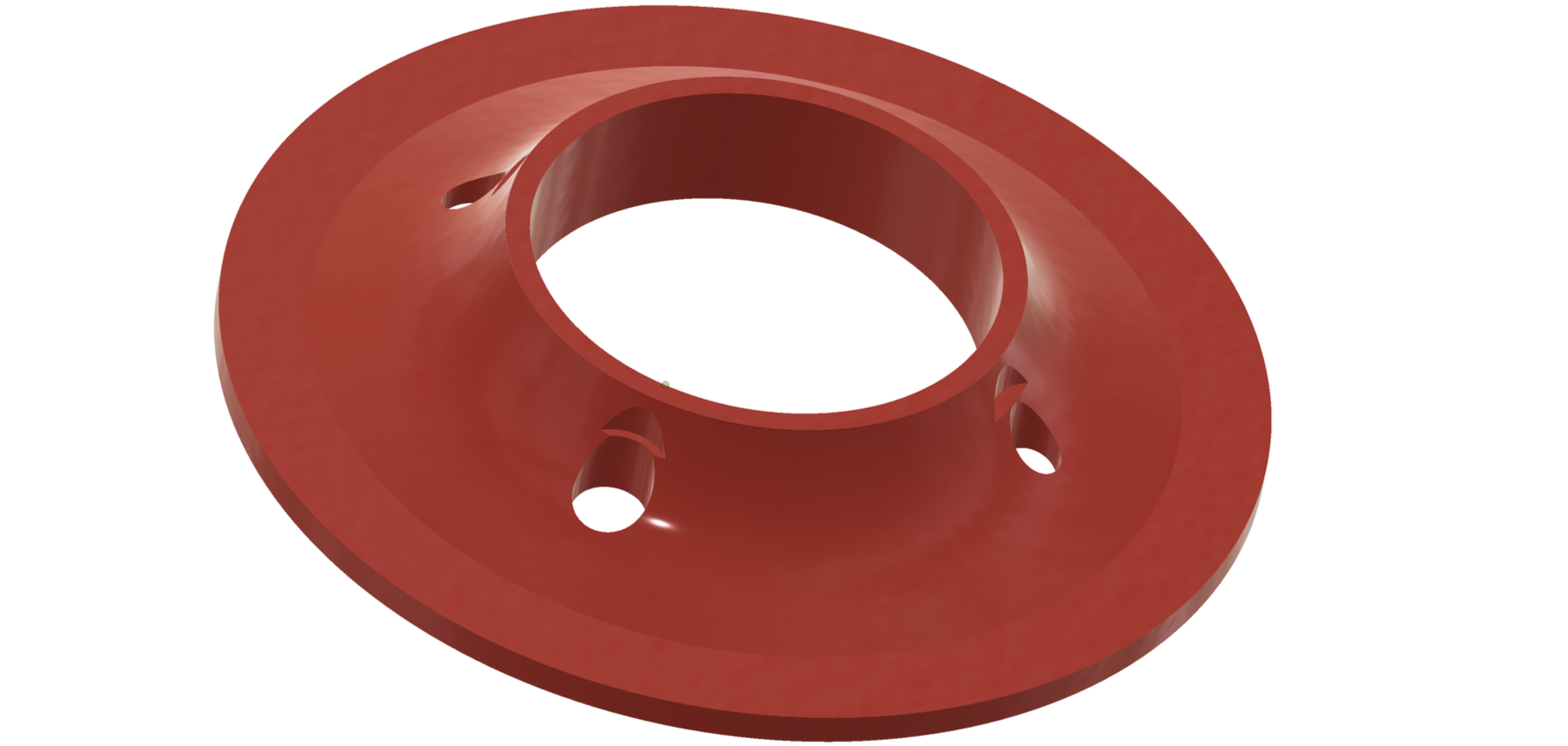
This is what an initial draft of the pedestal looks like. It’s actually quite a complex shape. It could be machined from a round bar and tapped (this is M6 but that could be M8 depending on how the pedestal is fixed to the hub), but it’s important that there is good surface connection between the pedestal and the hub and that the requires the pedestal to have this compound curve machined.
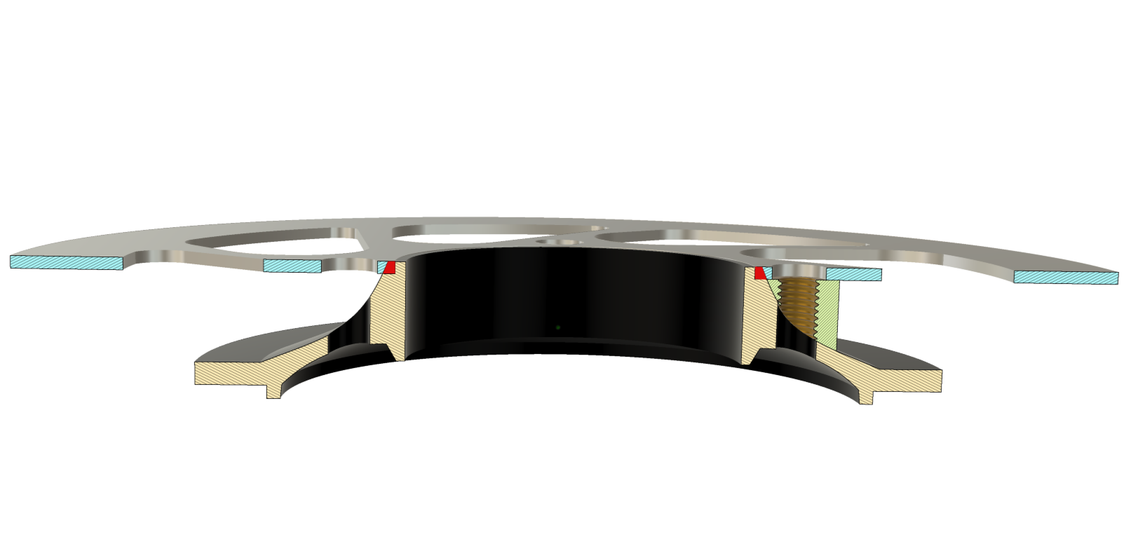
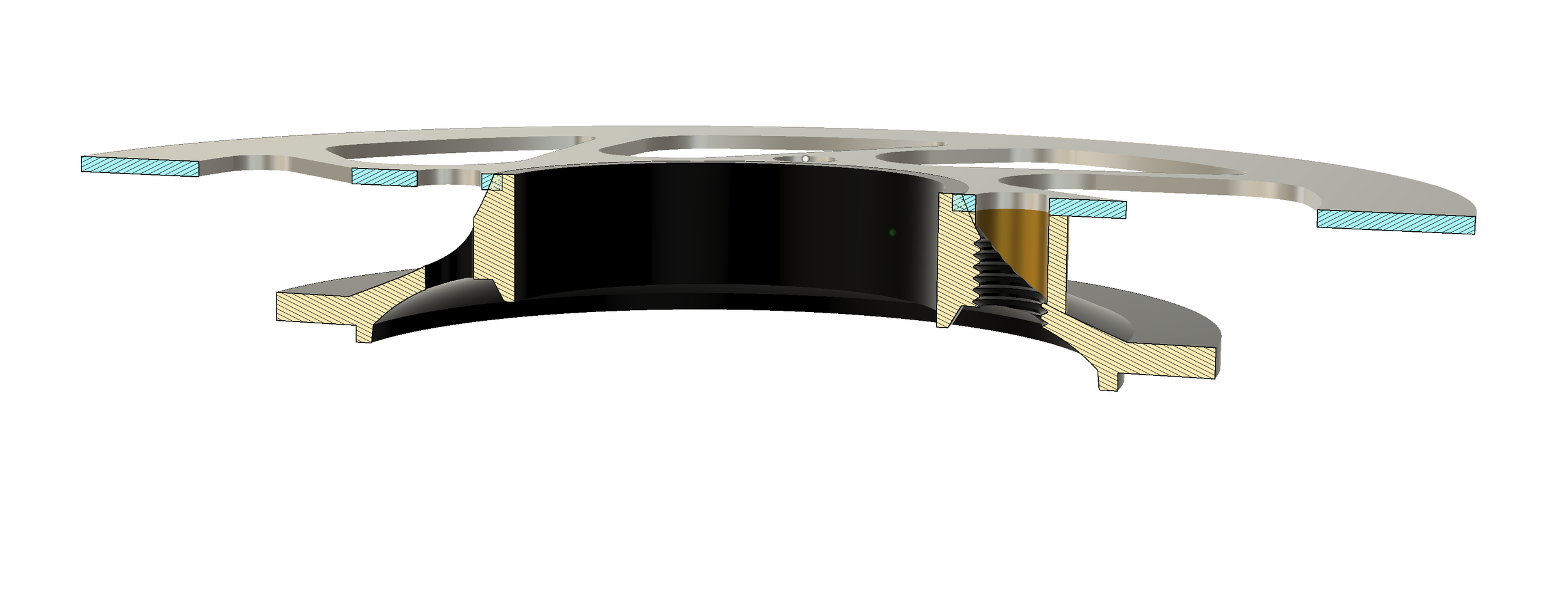
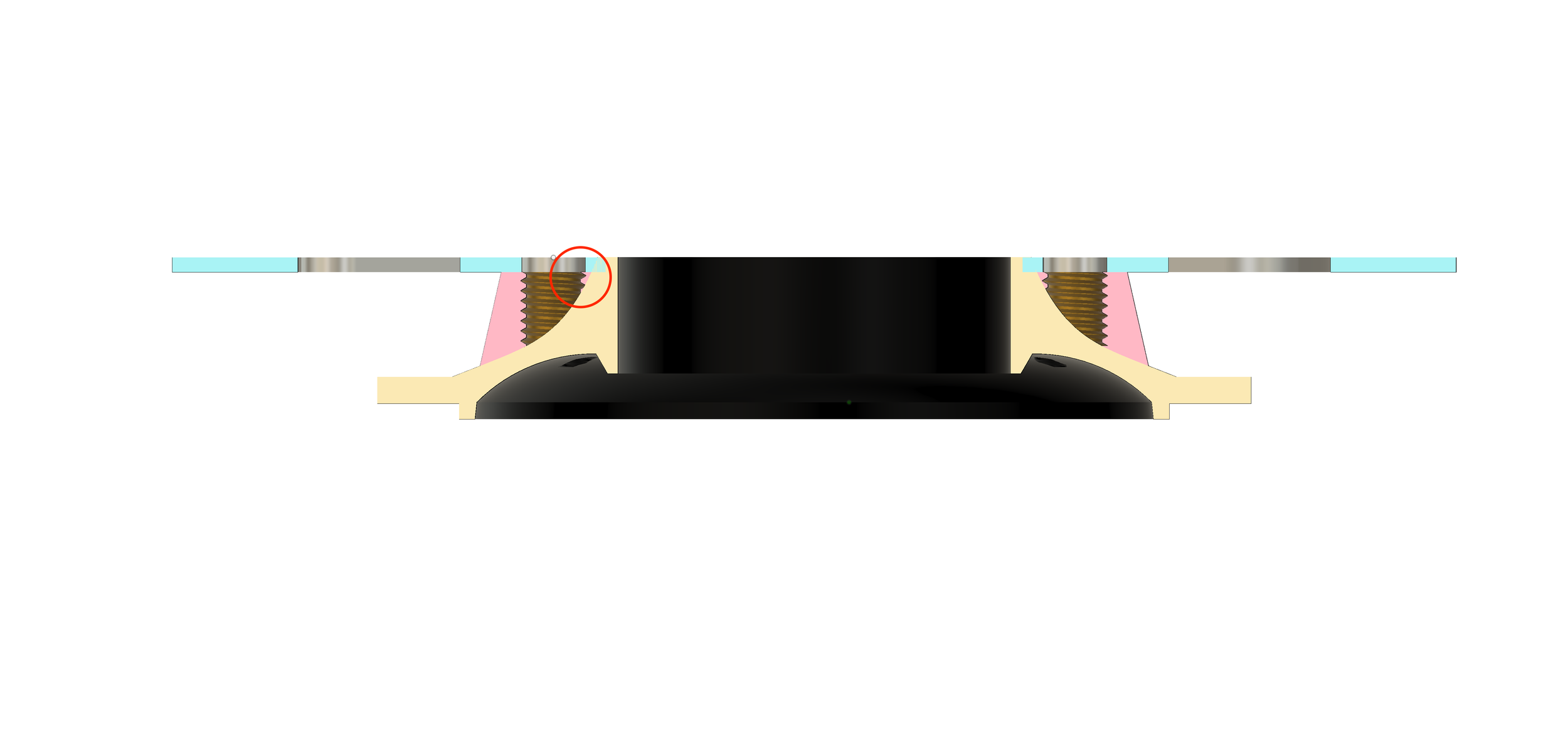
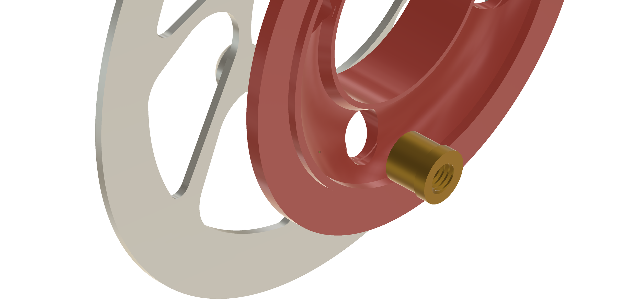
One of the first issues we’re going to run into is that if we try to use the standard Rohloff rotor and position it where it needs to be to be compatible with the rear disk brake standard, the rotor actually interferes with the hub shell. The centre bore of the rotor just isn’t big enough to slide over the end cap. You can see the interference on this cutaway (the area marked in red). It’s been suggested that we could just grind away the centre bore to provide clearance. This is certainly possible, however, it would bring the mounting holes pretty close to the edge of the rotor. Standard engineering principles suggest that the centre of holes like this should be at least 2 times their diameter (2d) away from an edge. If we grind away enough material to make it fit, we’d be only be about 5.5mm away from the edge. Much less than the suggested 16mm. That being said, I don’t think the holes on a non-modified rotor are 2d away from the edge before we start grinding, so who knows?

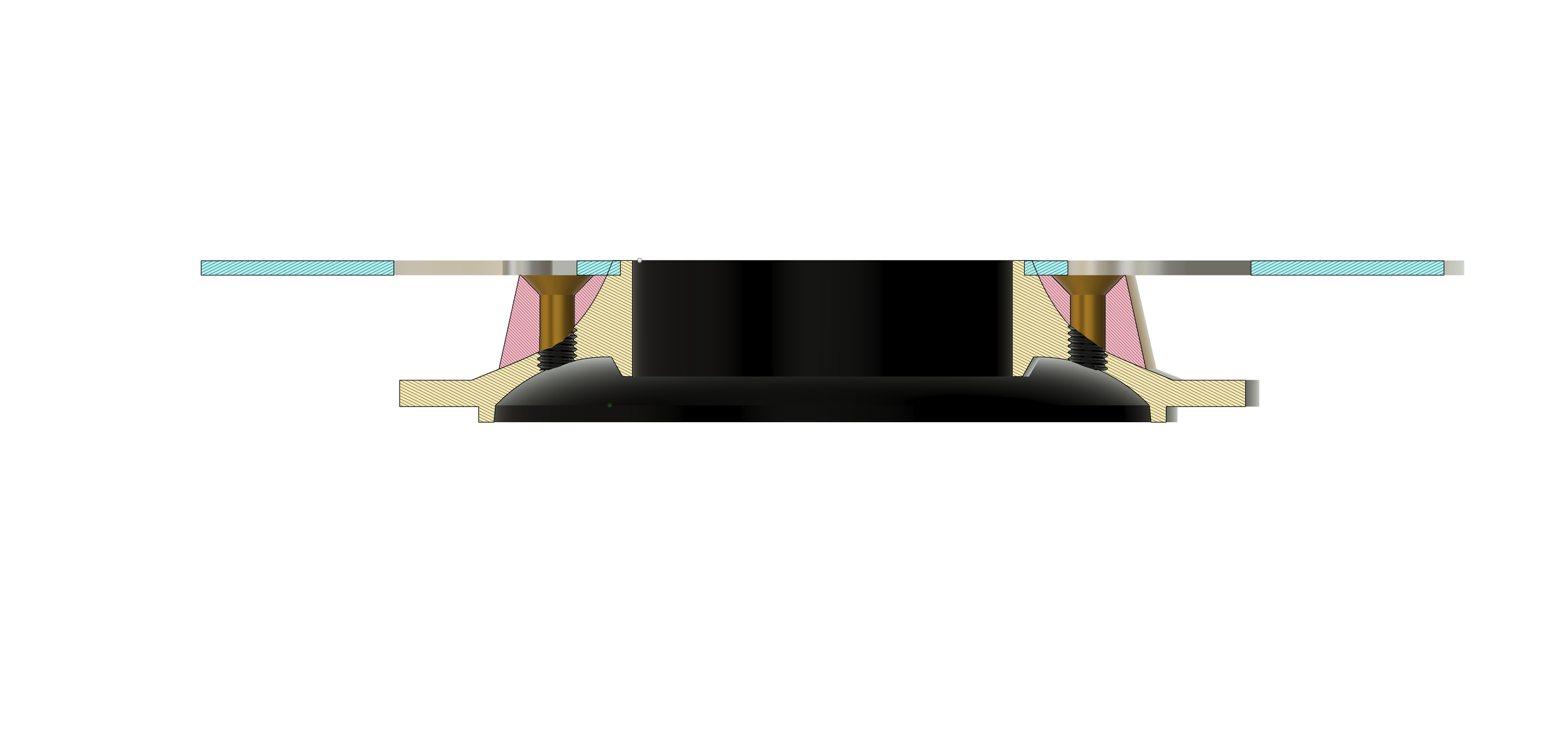
The two images above show a potential solution to mounting the pedestal. We tap the hub end cap (in this case M8 to match the rotor holes) and the pedestal just has a through hole. We can then use the fixing hardware that attaches the rotor to also attach the pedestal. While this looks like it could be a solution, you can see on the outside/lower part of the hub end cap, we only have a couple of threads due to the thin wall on on this part of the shell. I suspect that would be very easy to strip. I don’t think this is going to work.
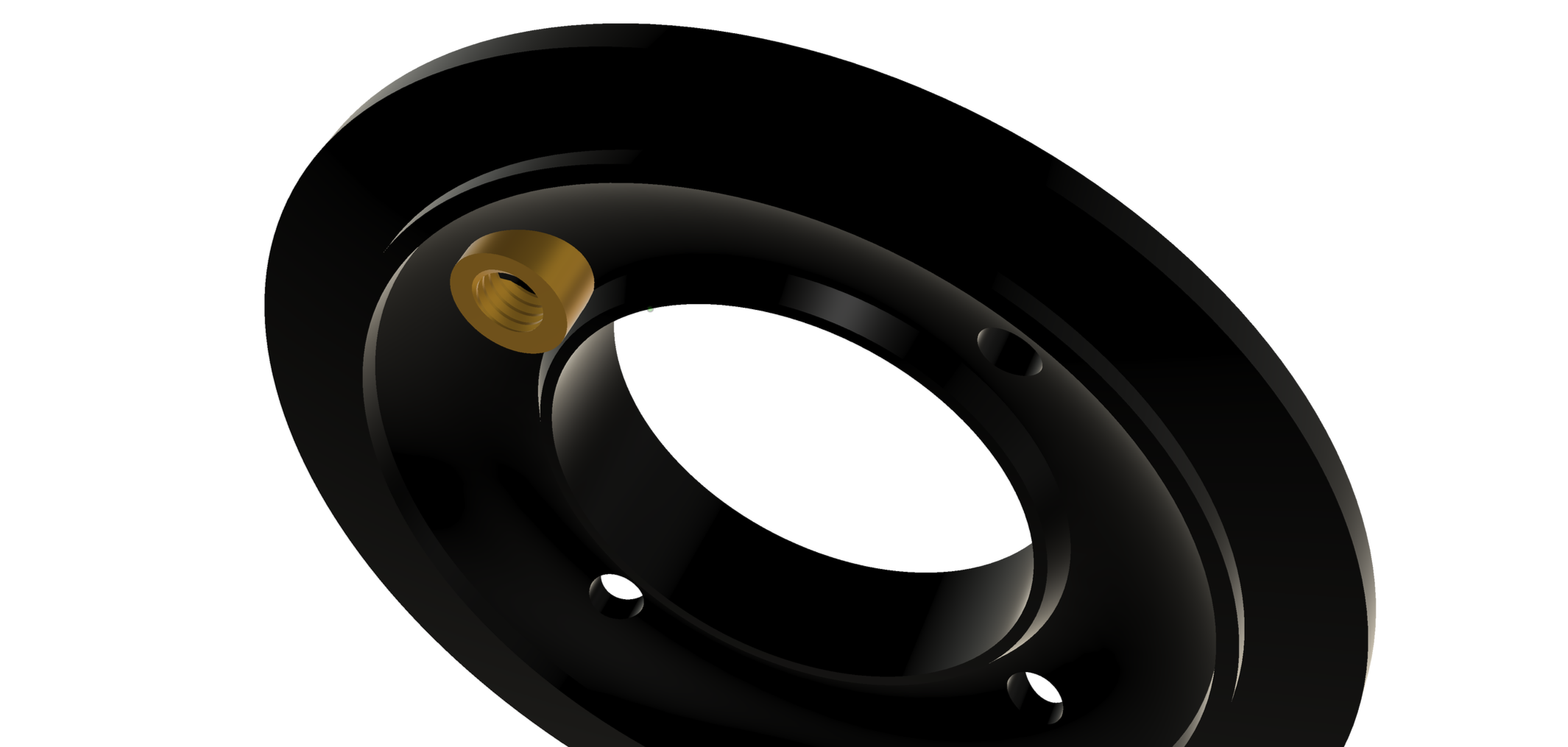
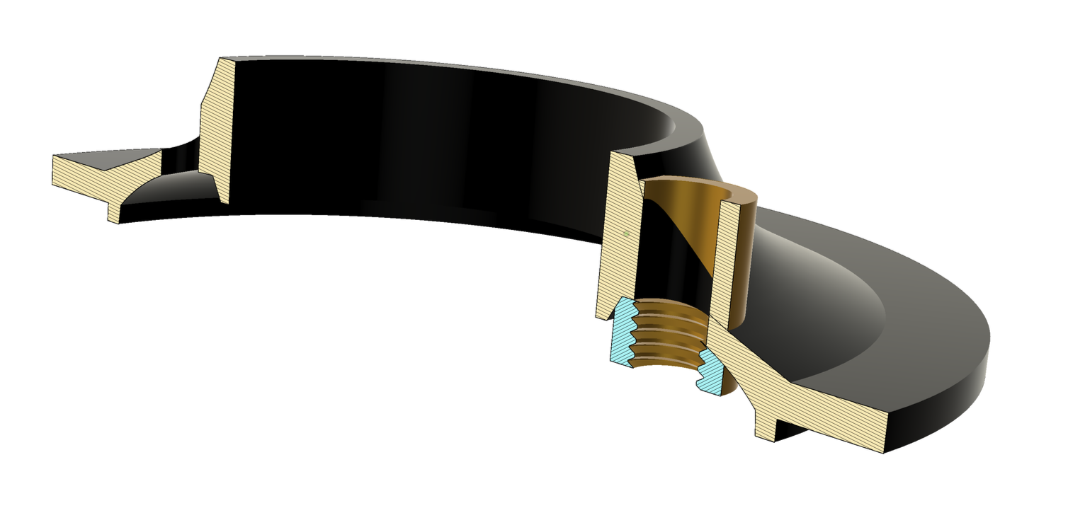
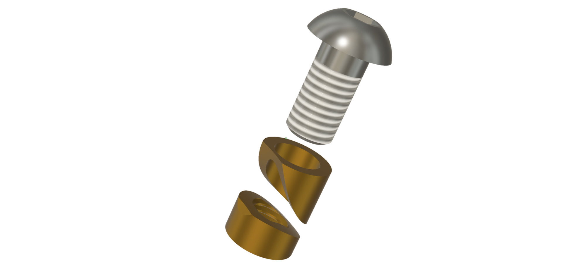
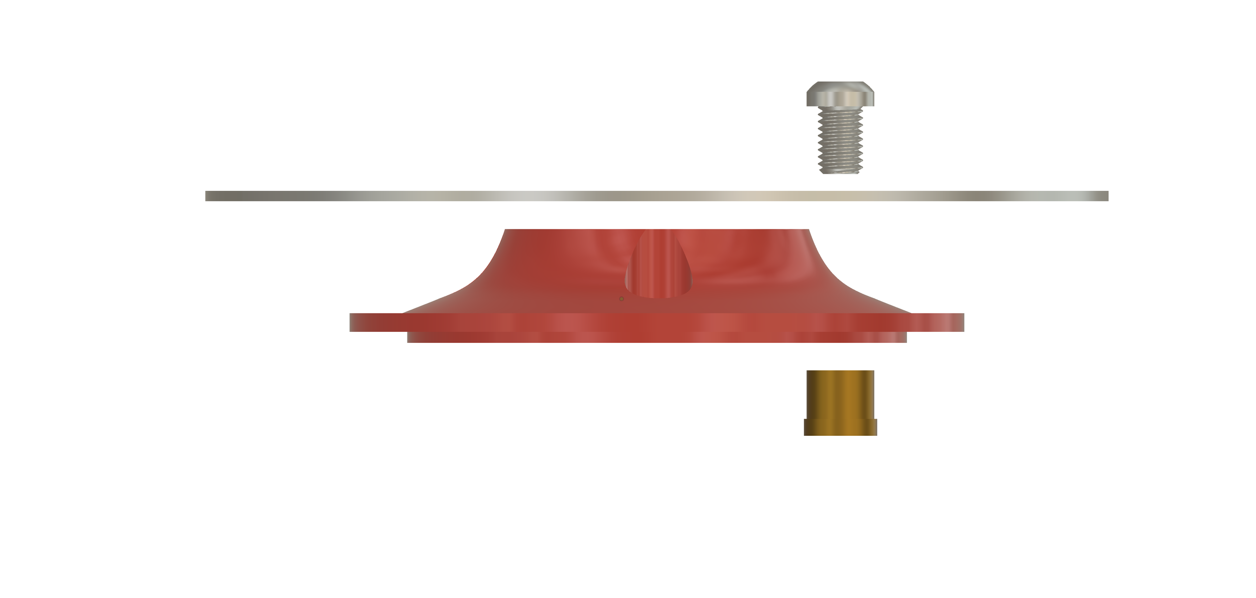
This is another approach to fixing the pedestal. Here we use a ‘nut’ on the inside of the shell. The rotor mounting hardware screws into this from above and through the outer pedestal. There’s a little more thread engagement on this one, but still not loads, and I’ve deliberately not checked the actual clearance we have inside the shell. I suspect there’s not enough for this, but it’s worth exploring, I think.
This is quite a nice solution but there are a few flaws.
Both the nut and the pedestal are quite complex shapes. They would be possible to make using handtools but in order to keep everything from coming loose, you’d want the profiles to sit as flush with the hub shell as possible. I think this would be a challenge.
If the nut were ever to come loose from the inside while riding, apart from the problems with the brakes failing, there’s a chance the nut could drop into the hub and damage the internals.
Swapping the rotor without having to access the inside of the hubshell could be a pain.
The next solution I’m going to explore is to mount a ring that goes all the way around the hubshell. This ring will have tapped M8 holes to allow the rotor to be attached. The ring will then be mounted to the shell by many smaller fixings (M5?). Perhaps tapped directly into the shell. The idea here is to decouple the way the rotor mounts, from the way the pedestal (or in this case, ring) mounts. It also means we won’t need access to the internals of the shell. I want to do some calculations that will guide how many fixings and what size they would need to be.
Stay tuned…..
ok, here’s a first run at a ring on the hub shell rather than just individual pedestals.
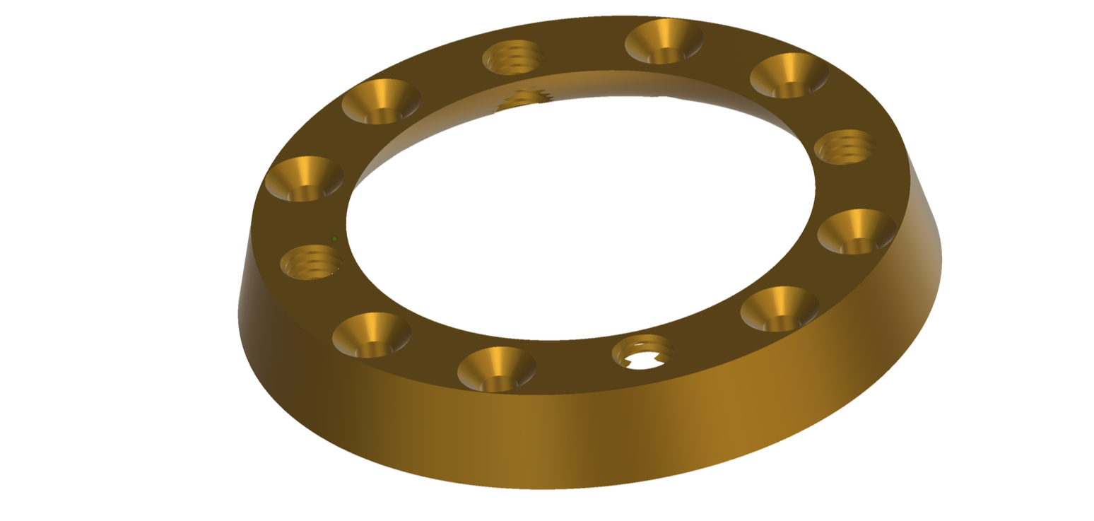
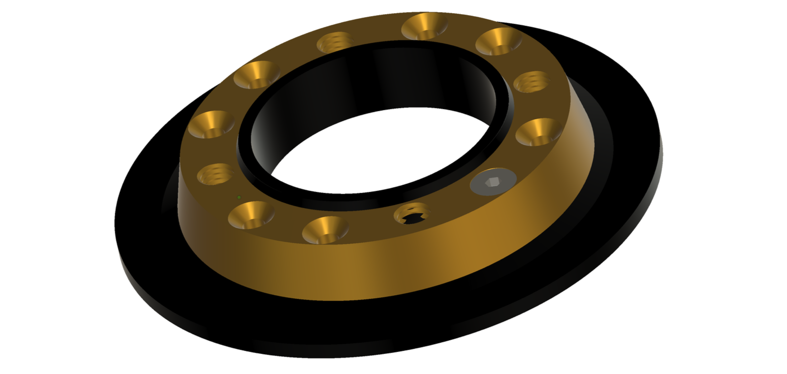
You can’t really tell from the images but the underside of the ring would be machined to the same profile as the hub shell. The ring is secured to the hub shell using 8 x M5 machine screws. In the drawing, you can see one of these screws but there would be 8.
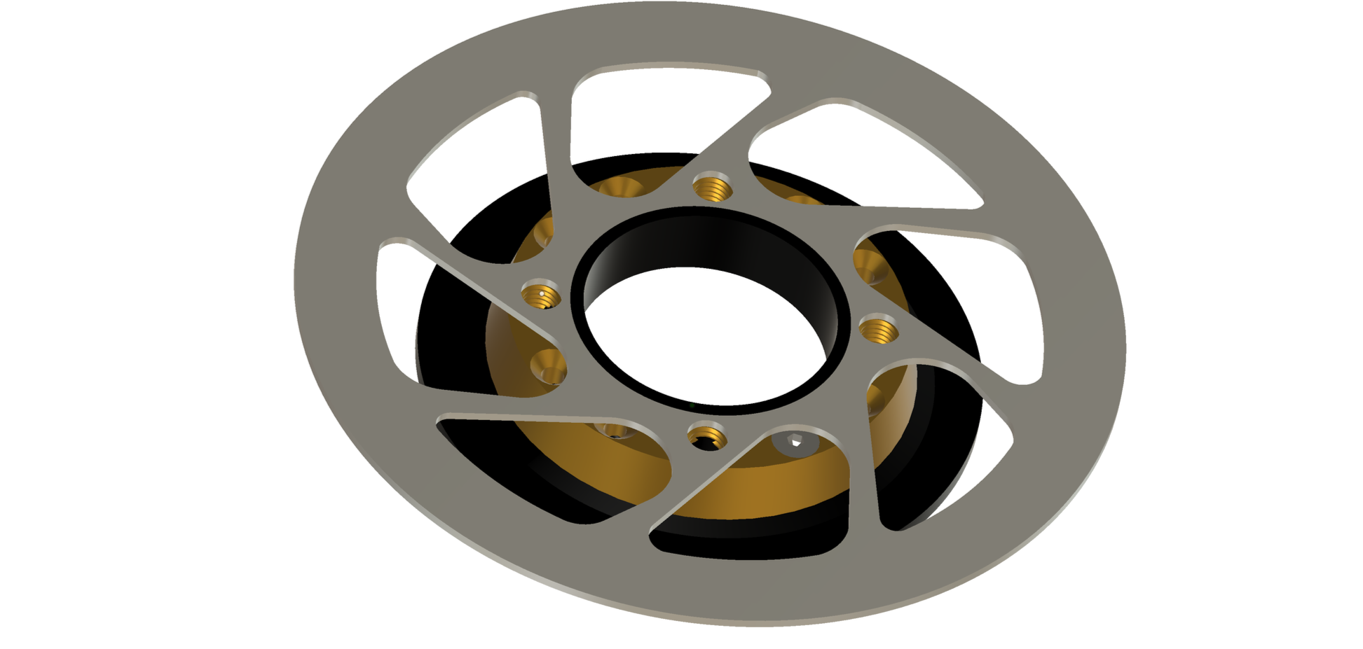
Because they’re countersunk, the rotor can be mounted flush with the top of the ring.
You can see here where the hub shell is tapped for the 8 x M5 machine screws. I’ll need to do calcs on this to see if that’s enough, but I suspect it is.
All that looks relatively promising, but if we look closer, we see that the M8 fasteners that hold the rotor to the ring do not have enough thread engagement (problem area circled in red).

We can improve on that by continuing the thread into the hub shell as per this drawing.
This would work. However, it’s crucial that the two threaded parts were tapped at the same time to keep the threads in sync. If we don’t do that the rotor fastener (M8 bolt) will bind up
Considering that one of the main requirements for this is that it should be easy to do (and I assume with handtools?) I think this would be a significant barrier to this approach.
Is this worth doing?
The original prompt for doing this piece of work came originally from a forum post (cyclinguk.org), where it was suggested that taking a non-disk Rohloff hub and just bolting on a disk rotor was a relatively straightforward task. I initially disputed this, but took some time to evaluate a couple of different solutions to see if, in fact, it would be a practical exercise.
The backdrop to this debate is that Rohloff (or a service centre) will convert a standard hub to a disk hub for you (at a cost, obviously, I think it’s somewhere around £135 now).
My gut feeling after spending some time looking at possible solutions is that it’s still a dumb idea.
The remaining ‘sticky’ issues for me include the following :
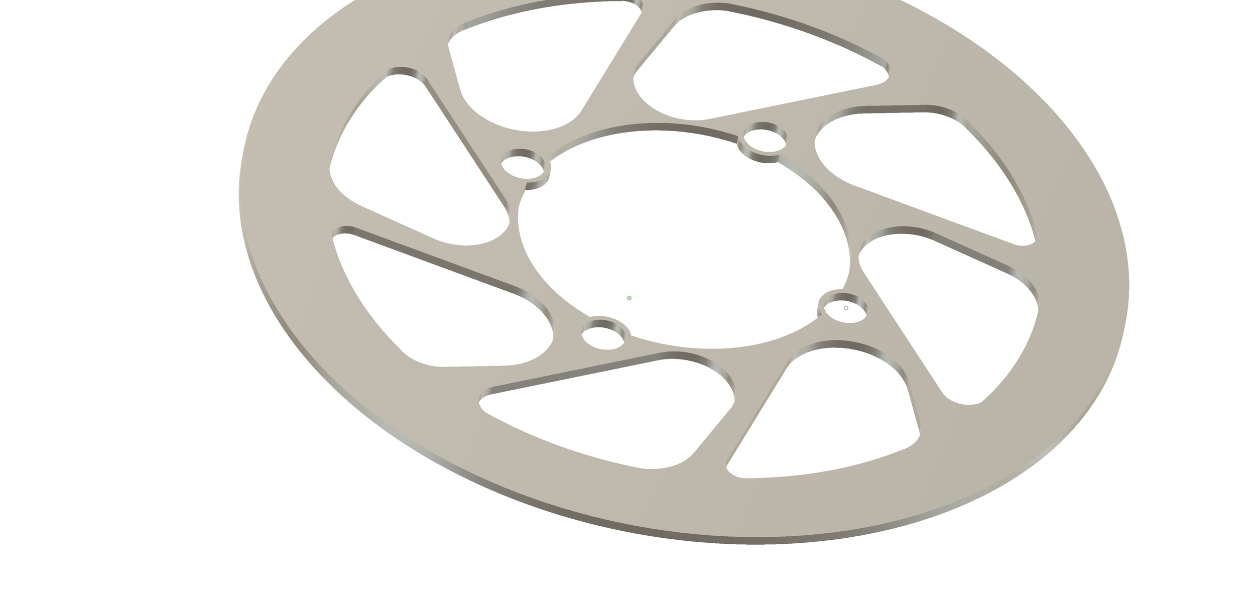
A standard Rohloff 4-bolt rotor will not fit onto the hub shell. The centre bore of the rotor is too small. The only workaround for this would be to increase the centre bore of the rotor or to move the rotor away from the standard position (further from the centreline of the bike). Increasing the centre bore isn’t really an option, as it would eat into the space required between the centre bore and the 8mm mounting rotor mounting holes. The centre bore would need to be at least 55mm to clear the hub shell, and this would leave only around 1mm between the edge of the mounting hole and the edge of the rotor. This isn’t enough. Moving the rotor outboard to clear the hub is an option. However, there’s no guarantee that the rotor would clear the frame. It’s pretty common for there to be very close clearance between the rotor and the frame. This will vary from frame to frame, though. Some may work better than others. If we did do this, we’d need a way to move the calliper outwards by the same amount as the rotor. There are a few brake mount standards, and each of them would create some difficulty in mounting a calliper further outboard than intended. Each standard would probably require a modified adapter. It may be helpful to increase the diameter of the rotor in use, as that would allow a little more room for modifications of the adapter, but that would increase the chance of frame/rotor clearance issues.
Whether we look at the 4 x pedestal solution or the single ring solution, the biggest barrier I see is the ability to manufacture the pedestals or the ring with the correct profile to securely mate to the curved surface of the hub shell. Getting the two mating surfaces to fit very accurately would be key to making sure the hardware did not work loose. This could obviously be done with a CNC machine; doing it manually with handtools would be more of a challenge. Especially creating 4 identical pedestals at the correct height.
Clearly, anything is possible given enough time/money/tools/skills, but after investigating a few possible options, I just don’t see a situation where attempting a DIY solution like this makes any sense. If there were no alternative, then perhaps you could argue it would be worth putting some time and effort into it, but because there is an off-the-shelf solution where the end product would be substantially better than a homegrown effort, I stand by my initial assertion that it’s a dumb idea.
Hold the front page! We’re not done……..


reference images
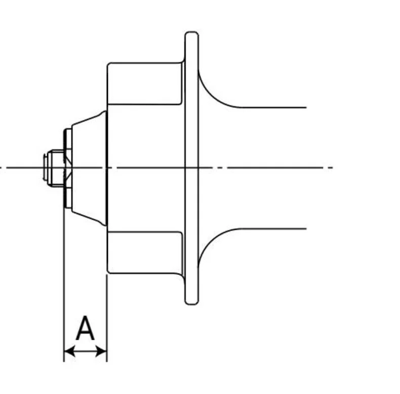
Rotor distance from the lock nut (assuming 10mm QR or solid axle) for dimension A is 15.25mm